
Battery energy storageTechnical pages
Integration and engineering of the BESS enclosure
The enclosure is drawn around the integrator's layout: where the cooling sits, where the cables enter, where the racks stand. Below is what Tanax engineers, what it prepares and what it integrates with partners.
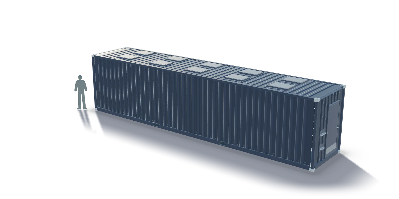
Framed openings with hoods
The openings for the HVAC or liquid-cooling units are framed and hooded, sized and placed to the integrator's units. The envelope keeps its class around them.
Gland plates
HV and LV gland plates with cable glands, separated, where the layout needs them. The sealed plates keep the enclosure tight and the cables where they belong.
What the engineering phase settles
The rack weights and the foot layout for the structural calculation; the transport loads and, where required, the seismic cases; the positions of the openings and the gland plates; the architecture, walk-in or non-walk-in; the corrosivity class; and the options the integrator wants fitted.
Systems with partners
HVAC or liquid cooling, fire suppression, off-gas detection, explosion-prevention ventilation, the BMS/EMS cabinet, auxiliary power, lighting and a fire brigade dry inlet are integrated with partners on request.
Series production
One design, calculated once, built as a series with an identical design across it and an inspection protocol with every unit. For battery OEMs the enclosure is white label.
Specification sheet
| Structure and floor | |
|---|---|
| Floor | 2,000 kg/m² standard, up to 3,000 kg/m² per structural calculation; local reinforcement under rack feet; cross members at tight pitch; 6 mm S355 steel deck seal-welded with no plywood, forming a liquid-tight tray for coolant or firewater; anchoring rails to the rack layout |
| Engineering | Structural calculation of the floor from rack weights and foot layout, including transport loads and seismic cases where required |
| Openings and fittings | |
| Technical openings | Framed openings with hoods for HVAC or liquid-cooling units; HV and LV gland plates with cable glands |
| Other | Earthing points, data plate, CSC plate, inspection protocol |
Figures are the published specification of the product family, not of a customer's design. Values marked per project are set in the engineering phase.
The specification sheet is generated from the same data as this page. It is sent with the reply to your enquiry and offered for download when the form is submitted.
Request the specification sheet (PDF)FAQ
Questions procurement asks
What do you need to start?
The rack weights and the foot layout, the cooling units and where they sit, the cable entries, and the site's corrosivity class. The structural calculation and the drawings follow.
Can the openings be moved later?
They are placed per design and welded in. A new position is a new drawing, so the layout is settled in the engineering phase.
Send the rack weights and the foot layout. The floor is calculated from them.
The structural calculation, the openings and the architecture are settled in the engineering phase. The specification sheet comes with the reply.
Related
Technical pages of this solution
- AI & DC PowerBattery storage enclosures engineered for heavy racks, thermal runaway and decades outdoors.
- Enclosure architecturesThe first decision of a battery enclosure is whether a person works inside it. Everything else, the doors, the lighting, the aisle, the rack count, follows from that.
- Fire and explosion safetyA battery enclosure is designed for the event nobody wants: cells venting, gas accumulating, a fire that has to stay inside a steel box. The design decisions below are what the enclosure contributes to the integrator's fire concept.
- Structure and floorA standard container floor is plywood on cross members. A battery rack stands on four feet and weighs what a loaded truck does. The floor is replaced, and the replacement is calculated.
- Corrosion and coatingA storage enclosure stands outdoors for the life of the asset. The coating system is chosen for the site's corrosivity class and applied in our own paint shop after our own blasting.
Related sectors